SPLiCE: Single-Point LiDAR and Camera Calibration & Estimation Leveraging Manhattan World
Gwangju Institute of Science and Technology (GIST)
School of Mechanical and Robotics Engineering

Abstract
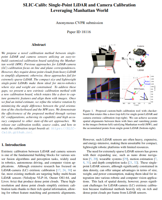
We propose a novel calibration method between single-point LiDAR and camera sensors utilizing an easy-to-build customized calibration board satisfying the Manhattan world (MW). Previous approaches for LiDAR-camera (LC) calibration focus on line and plane correspondences. However, they require dense point clouds from heavy LiDAR to simplify alignment; otherwise, these approaches fail for extremely sparse LiDAR. The compact size and lightweight single-point LiDARs make them ideal for micro-robotics where size and weight are constrained. To address these gaps, we present a new extrinsic calibration method with a new calibration board, which rotates like a door to capture geometric features and align them with images. Once we find an initial estimate, we refine the relative rotation by minimizing the angle difference between the grid orientation of the checkerboard and the MW axes. We demonstrate the effectiveness of the proposed method through various LC configurations, achieving its capability and high accuracy compared to other state-of-the-art approaches. We release our calibration toolkit, source codes, and how to make the calibration target boards at: SPLiCE Project Page.
Target Board
Custom-built calibration target board to extract point and line features: (1) Completely flat that satisfies the Manhattan world. (2) Multiple black-and-white grids row extend 300 mm horizontally, with a square hole at the lower center of the grid. (3) Rotates 90 degrees like a door. (4) Each frame has a unique Manhattan Frame.
Calibration Method
The single-point LiDAR provides only a distance value in a single direction. We utilize the square hole in the target board to extend the distance value into three points, requiring knowledge of both the grid and hole width. We can detect three points expressed in the LiDAR coordinate system for each frame. In the image from the camera, it perceives the square hole as a black grid due to the black wall visible through it and does not recognize it as an open hole.
SPLiCE Overview
Our main idea is to establish 2D-3D correspondences between the LiDAR and camera frames by inducing rotational motion on a new calibration target board.
Furthermore, we refine the relative rotation between two sensors by aligning the orientation of the calibration target board with respect to the MW axes.
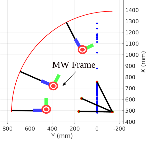
(red boxes) We detect three points based on the accumulated points from single-point LiDAR by utilizing the geometric characteristics of the proposed new calibration target board.
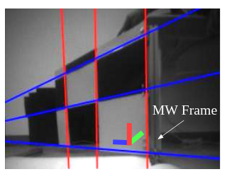
(green boxes) We extract three parallel vertical and horizontal lines in the image and detect the MW aligned to them.
(blue boxes) Given three points, parallel lines, and the MW, we find the relative rotation and translation between two sensors by minimizing the point-to-line distances and angle differences.
Result
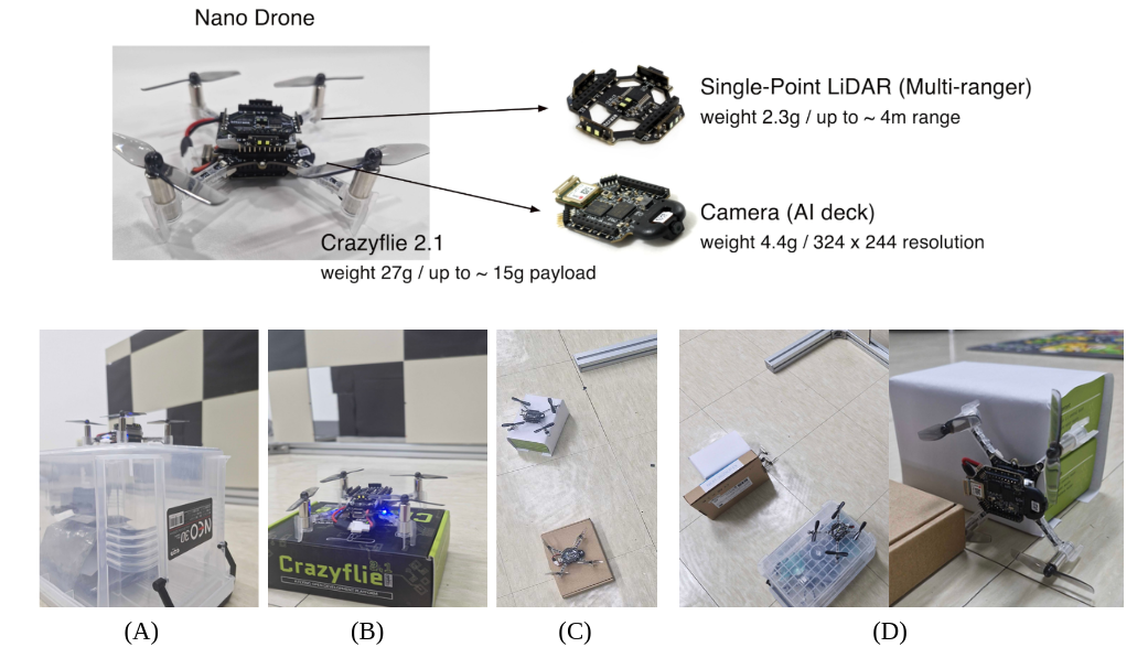
We evaluate four different configurations: intra-drone (A and B) and inter-drone (C and D) cases
Code and Datasets
Our calibration toolkit, code, and dataset will be released upon acceptance of our work.